
![]()
Thermoelectric Generators
Download #73: “Presentation-Development-of-a-New-Micro-CHP-Pellet-Stove-Technology-EUBCE2017.pdf”
Description of the biomass CHP technology based on a thermoelectric generator
The CHP technology based on thermoelectric generators is an innovative and interesting application for the generation of electricity from solid biomass in small boilers or stoves. The electrical power range is from a few Watts up to a few hundred Watts. Thus, the technology is particularly suitable to cover the own electricity consumption of the heat generation system. Thereby, a grid-independent operation of the heating system becomes possible and the reliability can be increased.
For the operation of a thermoelectric generator (TEG), in addition to the heat source (biomass boiler or stove), suitable thermoelectric modules with an appropriate power electronics as well as an adequate cooling system is required. The heat transferred to the cooling system can be used in a water circuit or directly released in the living room via convection air.
TEGs are a maintenance-free and noiseless technology without moving parts. Thus, this technology is particularly suitable to realise a grid-independent operation of stoves or boilers, which are usually installed in residential buildings. A useful thermal power range of the heating system for the use of a TEG is approximately 5 to 50 kWth.
Working principle and integration in a boiler or stove
The principle of the TEG is based on the Seebeck effect, in which heat is directly converted into electricity by two connected and differently doped semiconductors placed at different temperatures. In Figure 1 the general structure of a thermoelectric module is presented and Figure 2 shows a thermoelectric module with (left) and without (right) ceramic substrate.
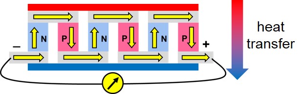
Figure 1: Schematic diagram of a thermoelectric module
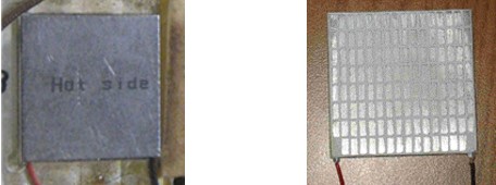
Figure 2: Thermoelectric module without (left) und with (right) ceramic substrate
The electric output of the TEG is influenced by the type of the thermoelectric modules, the number of modules used, the temperature difference between the cold and hot side of the modules (with rising temperature difference the electric output is increasing) and the cold side temperature of the modules (with rising cold side temperature the efficiency is decreasing). Thus, a high temperature difference between the cold and hot side combined with a low cold side temperature of the thermoelectric modules is aimed in order to achieve a high electric output of the TEG.
Since a good heat transfer on both sides of the TEG and a high heat transfer through the comparably small surface of the thermoelectric modules is essential for a high electric output, a special focus has to be put on the heating and cooling of the TEG. The hot side of the TEG is positioned in the flue gas path of the heating system. Thereby, high flue gas temperatures and a complete burnout of the flue gas before it passes the TEG are essential. To cool the cold side of the TEG different cooling options are possible:
- air cooling by natural convection or fan (relevant for stoves)
- cooling via heat storage (relevant for stoves)
- cooling with a water circuit (relevant for stoves and boilers)
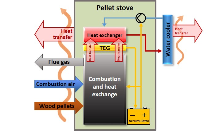
Figure 3: Schematic diagram of the integration of a TEG in a pellet stove
During operation of the boiler or stove the TEG supplies the heating system with electricity. Surplus electricity produced is stored in an accumulator (see Figure 3). The accumulator supplies electricity during the next start-up for the ignition and other power consumers (fan, fuel feeding and control system) until the TEG starts the electricity production. When the accumulator is fully charged, the electricity produced can also be used for other consumers (e.g. to charge external devices via an USB port). Thus, an important step towards a self-sustaining operation is to reduce the own electricity consumption of the heating system. This can be achieved by introducing a low voltage power system (TEG and accumulator are low voltage DC components), selection of appropriate components, as well as by optimisation of the system control.
Relevant technical data and efficiencies of thermoelectric generators
Since a high electric power output strongly depends on the temperature difference between cold and hot side of the thermoelectric modules an appropriate heating and cooling of the modules is essential (see Figure 4).
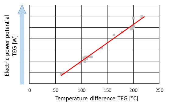
Figure 4: Dependence of the electric power of the TEG on the temperature difference between hot and cold side
Typical parameters of a TEG integrated in a biomass heating system:
- Flue gas temperature at the hot side of the TEG: up to 900°C
- Hot side temperature of the TEG: typically between 300 and 400°C
- Water/air inlet temperature to cool the TEG: 30 - 50°C
- Cold side temperature of the TEG: down to 40°C
- Applicable power range of the heating system: 5 – 50 kWth
- Applicable power range of the TEG: some hundred Watt
- Electric efficiency (based on the thermal power input into the TEG): 2 – 5%
Realised projects and further information regarding the thermoelectric generator
BIOS in co-operation with the pellet stove manufacturer RIKA has successfully developed and tested a TEG technology for pellet stoves within the ERANET project „Small-scale biomass based CHP“. It could be shown that the TEG is able to produce more electricity than consumed from the pellet stove, thus an energy independent operation of the pellet stove is possible and even some excess electricity is produced which can be used for charging mobile phones for instance.